Mixing Process Station
Description
The mixing process station mimics the industrial chemical mixing process using programmable logic controllers (PLC). Water from the supply tank will be pumped to two overhead tanks and then filled to the process tank through solenoid valves. The quantity of fluid from each tank can be controlled by the time activation of the solenoid valves, which can be set by the user in the program. After a delay the mixer motor
will be activated for a particular preset time. The station consists of the following components and the schematic of the station is given below:
− Supply Tank
− Overhead Tank – 2 Nos.
− Pump
− Mixer motor
− Solenoid Valve – 4 Nos
− High & Low level switches.
Features
Onboard PLC
Uses only Digital I/Os
Standalone table top design
Build in control panel
Patch cords interfacing
Discrete unit programming and validation
Range of Experiments
- Study of Bit Logic (NO, NC, NOT, etc..), Timer (TON, TOFF, TONR, etc..), Comparators (>=, <=, ==, etc….), Counters (CU, CD, CUD)
- Level on/off control
- Pump on/off control using timers
- Mixer tank water level control using solenoid and timers
- Mixer motor operation using timers
- Mixer tank drain using timers
Operation & Control outline:
i. Supply Tank Level Control:
The Supply tank is connected to continuous water supply line and controlled by solenoid valve. It is fitted with high and low level float switches which directly controls the inflow to the tank using a solenoid valve.
ii. Overhead Tank Filling:
This is a timer based operation. The pump on the Supply tank will be running for every 10secs in an interval of 20 secs. These timings can be user defined.
iii. Mixer tank filling:
Two solenoid valve controls the inflow to the mixer tank. Filling duration can be controlled by a timer. The filling can also be alternate. First solenoid can be opened for 20 seconds and the mixer motor is allowed to run for 1 minutes. Later, the second solenoid can be opened for 30 seconds and again the mixer motor will
be on for another 1 minutes. After this operation, a delay of 2 seconds can be given and the drain solenoid will be opened for 1 minutes. This operation can be repeated until the Mains switch is ON.
Interlocks:
1. If level low switch (LLS) is ‘High’, SV1 is ON. Start a timer. If still low for 10secs, pump, conveyor, SV2 remains off after completing current cycle. Will get reset once LLS is low.
2. Auto / Manual switch can be used to switch from Auto cycle to Manual mode. In manual mode, all the outputs can be activated manually.
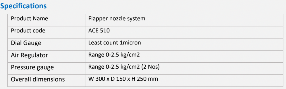
Specifications
- Product Mixing Process Station
- PLC Make: Delta
- CPU Model: PLC – DVP20EX200 R/T, I/Os: 8DI, 6DO, 4AI, 2AO with Modbus and 485 Communication
- Digital Input / Output On board, 24 input points / 16 output points, 24V DC
- Analog Input No. of Inputs: 4, Type:
- Voltage or current (differential),
- Range: ±10 V, ±5 V, ±2.5 V, or 0 ~ 20 mA
- Resolution: Voltage mode: 11 bits + signal bits,
- Current mode: 11 bits
- Analog Output No. of Outputs: 2, Type: Voltage or current, Range: ±10 V or 0 ~ 20 mA,
- Resolution: Voltage mode: 10 bits + signal bits,
- Current mode: 10 bits
- Communications 1 serial (RS485) / 1 RJ45
- Converter RS 485 to USB with isolator
Power source 230 V AC
Product Specifications